Pearson Edexcel International GCSE in Physics · 4PH1 · Free · no account needed
Current–Voltage Graphs, LDRs and Thermistors
The shapes four components make on a graph, and two resistors that deliberately refuse to stay the same.
Topic 2 · Electricity — one of 9 lessons in this topic, and one of 65 in Physics.
This lesson ends with Humphry Davy. Learn Current–Voltage Graphs, LDRs and Thermistors, teach it, then defend it against Humphry Davy.
The definition this lesson teaches, word for word — every Physics definition.
- Current–voltage characteristic
- A graph of the current through a component against the voltage across it. Its shape shows whether the component's resistance is constant, and how it changes if it is not.
One of the 17 Physics required practicals.
What this lesson covers in the specification
Incandio is aligned to this specification. It is not published by, endorsed by or affiliated with Pearson, and it reproduces none of Pearson's wording — the statement numbers are given so you can check every lesson against your own copy.
- 2.9 — How current varies with voltage in wires, resistors, filament lamps and diodes, and how to investigate it
- 2.11 — How the resistance of LDRs varies with light and thermistors with temperature
- 2.12 — Lamps and LEDs indicate the presence of a current
Specification section 2(b) Mains electricity — also taught in Resistance and Ohm's Law, Series and Parallel Circuits, Electrical Power and Energy, Mains Electricity and Safety.
1 · Understand it
No exam language yet. The only question this section answers is: do I actually understand what is happening?
Take any component, vary the voltage across it, measure the current through it at each setting, and plot the results. The shape of the graph is a fingerprint: it tells you whether the resistance is constant, and if not, how it changes. Four shapes are examinable and each says something different.
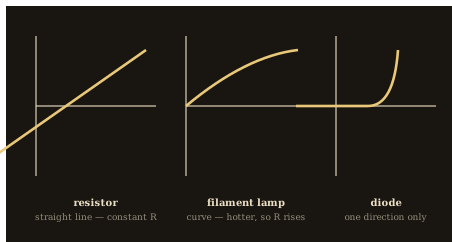
The four characteristic shapes, and what each means
- A FIXED RESISTOR or a metal WIRE at constant temperature gives a STRAIGHT LINE THROUGH THE ORIGIN, in both directions. The resistance is constant, so current is proportional to voltage: this is an ohmic conductor.
- A FILAMENT LAMP gives an S-shaped curve that flattens as the voltage increases. As more current flows the filament heats up, the lattice ions vibrate more, collisions are more frequent, and the resistance RISES — so the current increases less and less steeply.
- A DIODE gives almost NO current in one direction at all, and a sharp rise in the other once the voltage passes about 0.6 V. Its resistance is very high one way and low the other, so it allows current in one direction only.
- An LED behaves like a diode and emits light when current passes, which is the point of statement 2.12 — a lamp or an LED in a circuit shows at a glance whether a current is flowing.
- In every case, read the resistance at any point as V ÷ I for that point — not as the gradient, which is a common and expensive mistake on a curved graph.
That last warning deserves its own sentence. On a current–voltage graph with current on the vertical axis, the resistance at any point is the VOLTAGE DIVIDED BY THE CURRENT at that point — that is, V ÷ I read off the axes. It is the reciprocal of the gradient, and only for a straight line through the origin do the two give the same answer everywhere. On the curve of a filament lamp, taking the gradient will give a different value at every point and none of them will be the resistance.
Now two components chosen precisely because their resistance is not constant, and whose usefulness comes from that. A THERMISTOR is a resistor whose resistance falls sharply as its temperature RISES. An LDR — a light-dependent resistor — is one whose resistance falls sharply as the light falling on it gets BRIGHTER. Both are the same idea: turn a physical condition into a resistance, so a circuit can respond to the world.
Think of it like a door that opens itself as the room fills
Imagine a doorway that automatically widens as more people crowd towards it, and narrows again when they disperse. Nothing chooses to open it; the width is simply a function of the conditions. A thermistor and an LDR are doorways of that kind for electric charge. Heat the thermistor and its doorway widens, so more current flows without anyone adjusting anything. Shine light on the LDR and the same thing happens. This is why they are the input components of almost every automatic circuit — a fire alarm, a thermostat, a street lamp that comes on at dusk — because they make the circuit's behaviour depend on a condition rather than on a switch.
Be careful with the direction of both relationships, because both run the opposite way to the intuition. HOTTER means LOWER resistance for a thermistor — which is the opposite of what happens to a metal wire, where heating raises the resistance. BRIGHTER means LOWER resistance for an LDR. The way to remember it without confusion is to think about what the device is FOR: a street lamp must switch on in the DARK, so darkness has to be the condition that produces the high resistance and hence the large voltage across the LDR.
Reading a resistance off an I–V graph
A filament lamp carries 0.20 A when the voltage across it is 2.0 V, and 0.50 A when the voltage is 8.0 V. Find its resistance at each point and say what is happening.
- At the first point: R = V ÷ I = 2.0 ÷ 0.20 = 10 Ω.
- At the second point: R = V ÷ I = 8.0 ÷ 0.50 = 16 Ω.
- The resistance has risen from 10 Ω to 16 Ω.
- The filament is hotter at the higher current, so the lattice ions vibrate more, electrons collide with them more often, and the resistance is greater.
Answer: 10 Ω and then 16 Ω — the same component with two different resistances, which is exactly why it is not ohmic.
2 · Grade 9 Notes
A different job from the section above. You have already understood it; this is the precise set of things to LEARN — definitions to reproduce word for word, processes in order, equations with units, and the answers that score full marks.
The four I–V characteristics — the shapes and what they mean
| Shape of the graph | What the resistance is doing | |
|---|---|---|
| Fixed resistor / metal wire | straight line through the origin, both directions | constant — current is proportional to voltage; it is ohmic |
| Filament lamp | S-shaped curve, flattening as voltage rises | increases as the filament heats up |
| Diode | almost zero one way; sharp rise above about 0.6 V the other way | very high in reverse, low in forward |
| LED | the same shape as a diode | the same as a diode, and it emits light when current flows |
Learn this definition · Current–voltage characteristic
A graph of the current through a component against the voltage across it. Its shape shows whether the component's resistance is constant, and how it changes if it is not.
The components that change on purpose
- Thermistor
- A resistor whose resistance FALLS as its temperature RISES. Used in thermostats and fire alarms.
- LDR
- A light-dependent resistor: its resistance FALLS as the light on it gets BRIGHTER. Used in street lights and camera exposure circuits.
- Diode
- A component that allows current in one direction only, with a very high resistance in reverse.
- LED
- A diode that emits light when a current passes through it in the forward direction.
- Ohmic conductor
- A component whose resistance stays constant, so its I–V graph is a straight line through the origin.
Investigating how current varies with voltage (statement 2.9)
- Connect the component in series with a battery, an ammeter and a variable resistor, and connect a voltmeter in parallel across the component.
- Adjust the variable resistor to give the smallest voltage reading and record the voltage and the current.
- Increase the voltage in equal steps, recording the voltage and the current at each step, for at least six values.
- Switch off between readings so the component does not heat up more than necessary.
- Reverse the connections to the supply and repeat, so that the graph can be plotted in both directions.
- Plot current on the vertical axis against voltage on the horizontal axis and draw a smooth curve or line of best fit.
Variables
Independent (changed) — The voltage across the component, in volts
Dependent (measured) — The current through the component, in amperes
| Control variable | Why it must be held constant |
|---|---|
| The same component | a different component has a different characteristic |
| Temperature | resistance changes with temperature in most components |
| The same meters | different meters have different systematic errors |
Sources of error
| Type | What goes wrong | What to do |
|---|---|---|
| Systematic | The meters do not read zero when disconnected, so every reading is shifted by the same amount. | Check and zero both meters before starting. |
| Systematic | Current is left flowing between readings, so the component heats up and its resistance rises. | Switch off between readings. |
| Random | The reading fluctuates while the variable resistor is being adjusted. | Wait for the reading to settle before recording it. |
Finding the resistance from a current–voltage graph
- Choose the point on the graph you have been asked about.
- Read the voltage and the current at that point from the two axes.
- Calculate R = V ÷ I using those two values.
- Do NOT use the gradient: on a curve it gives a different quantity, and only on a straight line through the origin do the two agree.
The two ways resistance changes with temperature
A. A METAL WIRE or filament: resistance RISES as temperature rises, because the lattice ions vibrate more and collisions become more frequent.
B. A THERMISTOR: resistance FALLS as temperature rises, because more charge carriers are released. It is deliberately made from a semiconductor for this reason.
Model answer [4 marks]
Explain why the current–voltage graph for a filament lamp is a curve rather than a straight line. [4]
As the voltage across the lamp increases, the current through the filament increases and more energy is transferred to it each second, so the filament gets hotter. The positive ions in the metal lattice vibrate more violently, so the drifting electrons collide with them more frequently and the resistance of the filament increases. Because the resistance is not constant, the current does not rise in proportion to the voltage, and the graph curves and flattens instead of remaining straight.
Model answer [4 marks]
Describe how the resistance of an LDR and of a thermistor change, and give one use of each. [4]
The resistance of an LDR decreases as the light falling on it becomes brighter, and increases in the dark. It can be used in a circuit that switches a street light on automatically when it gets dark. The resistance of a thermistor decreases as its temperature rises, and increases as it cools. It can be used in a thermostat or a fire alarm, where the circuit responds when the temperature rises.
Not this: The resistance at a point on an I–V graph is the gradient of the graph there.
This: It is V ÷ I read off the axes at that point. With current on the vertical axis the gradient is I ÷ V, the reciprocal of the resistance — and on a curve it gives a different value again.
Mark-losing trap. Thermistor: HOTTER means LOWER resistance. That is the opposite of a metal wire.
Mark-losing trap. LDR: BRIGHTER means LOWER resistance. In the dark its resistance is high.
Mark-losing trap. Read resistance as V ÷ I at a point — never as the gradient of a curved graph.
Mark-losing trap. A diode conducts one way only, and needs about 0.6 V before it conducts at all.
3 · Prove it — the five questions
The five questions climb Grade 6 → Grade 7 → Grade 8 → Grade 9 → Grade 9 challenge, and are marked inside Incandio on your own device, by rule, with an authored diagnosis of the mistake you actually made. The mark schemes stay in the app so that the practice is worth doing; the questions themselves are here.
- Grade 6 · State [1 mark] — What happens to the resistance of a light-dependent resistor when the light falling on it gets brighter?
- Grade 7 · State [2 marks] — Which of these describes the current–voltage graph of a fixed resistor kept at a constant temperature?
- Grade 8 · Calculate [3 marks] — At one point on its characteristic, a filament lamp carries a current of 0.25 A when the voltage across it is 6.0 V. Calculate its resistance at that point.
- Grade 9 · Describe [6 marks] — Select every statement that belongs in a full-mark description of how to investigate the way current varies with voltage for a filament lamp.
- 9+ · Analyse [6 marks] — A student says: 'A metal wire and a thermistor are both just resistors, so heating either of them will do the same thing.' Select every statement that belongs in a full-mark analysis.
The people behind this science
Two ways into the same idea — the one who explained why light can change what a material does, and the one who found a substance whose resistance fell as it got hotter. Inside Incandio each of them answers knowing exactly which lesson you have just finished.
Albert Einstein — the one who explained why light can change what a material does
An LDR works because light falling on a semiconductor frees charge carriers inside it, and the fact that light can do this at all was the puzzle Einstein solved in 1905. The photoelectric effect showed that light delivers its energy in discrete packets, and that whether an electron is freed depends on the frequency of the light rather than on how bright it is — a result so strange that it, and not relativity, is what his Nobel Prize was awarded for. The component on this page is that discovery turned into a five-pence part.
- “How can light falling on a material make it conduct electricity better?”
- “Why does the colour of the light matter more than its brightness?”
- “What made the photoelectric effect so difficult to explain?”
- “Why was this the work your Nobel Prize was given for?”
- “What is happening inside the material when the light strikes it?”
Michael Faraday — the one who found a substance whose resistance fell as it got hotter
In 1833 Faraday noticed that silver sulphide conducted BETTER as it was heated, which is the opposite of every metal and was, at the time, inexplicable. It is the first recorded observation of semiconductor behaviour — the same behaviour a thermistor is built to exploit — and he recorded it carefully without being able to account for it. He is the right person on this page for the habit it teaches: the anomalous result that will not fit is usually the one worth keeping.
- “What did you notice about silver sulphide when you heated it?”
- “How do you treat a result that contradicts everything else you know?”
- “Why would heating a substance ever make it conduct better?”
- “How much of your work came from following up something odd?”
- “What would you want to measure about such a material next?”
Think you understand it?
Reading is the start. On Incandio a topic counts as mastered only once you have taught it and defended it — the two things a revision guide cannot ask of you.
Incandio this topic → Prove it. Teach it. Defend it. What does “Incandio it” mean?
- Prove it — five questions on Current–Voltage Graphs, LDRs and Thermistors, marked on the spot, that tell you what was missing rather than just what was wrong.
- Teach it — Explain Current–Voltage Graphs, LDRs and Thermistors in your own words to Ember, an AI pupil who does not have it yet and asks the awkward question. Understanding is credited; wording is not required.
- Defend it — Argue Current–Voltage Graphs, LDRs and Thermistors against Humphry Davy — three rounds, marked against descriptors you can read before you begin.
- Then the exam — read all 12 authored exam-style questions on this unit, each with its command word and its tariff, then have them marked on Incandio with the mistake you actually made named.
Completely free. No subscriptions, no paywalls, no account needed to start.
Carry on through the course
- Previous lesson: Series and Parallel Circuits
- Next lesson: Voltage as Energy per Charge
- Charge and Current — What is actually moving in a wire, how fast it is really going, and why the arrows on every circuit diagram point the wrong way.
- Resistance and Ohm's Law — What slows the electrons down, the one equation that ties the whole topic together, and when it stops being true.
- Series and Parallel Circuits — Two ways of joining components, and why every building in the world is wired one of them.
- Voltage as Energy per Charge — What a volt actually is — and why knowing that turns three separate equations into one idea.
- Electrical Power and Energy — Why a wire carrying a current gets hot, how fast a device uses energy, and how to pick a fuse.
- All of Physics · Physics key terms · required practicals · equations · Incandio Science · The 4PH1 specification